DYX2013 Moving Beam Dual-Drive Gantry Machining Center Technical Description
I. Machine Characteristics
-
The DYX2013 moving beam, dual-drive CNC gantry milling machine features a fixed table and a moving gantry utilizing dual-drive technology, offering large load capacity and a small footprint.
-
The moving beam design provides a relatively stable moving mass, resulting in less wear on ball screws and guideways, and extending the overall machine service life.
-
This model achieves optimal machining performance within a vertical (Z-axis) travel range of 300~400mm.
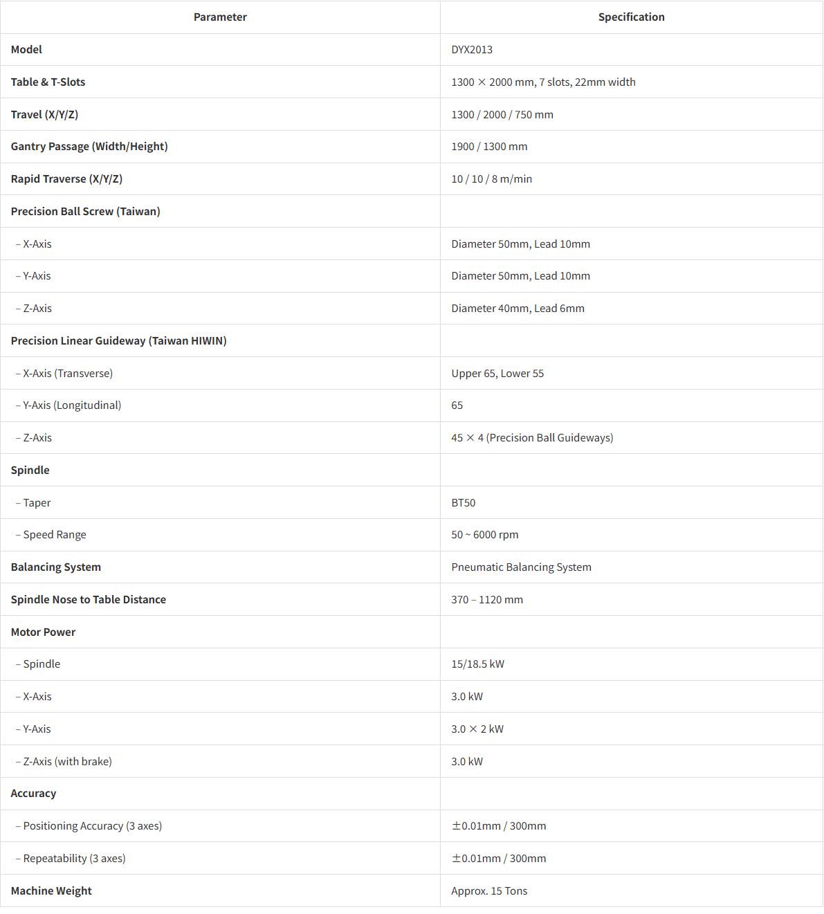
II. Main Configuration and Technical Parameters
| Parameter | Specification |
|---|---|
| Model | DYX2013 |
| Table & T-Slots | 1300 × 2000 mm, 7 slots, 22mm width |
| Travel (X/Y/Z) | 1300 / 2000 / 750 mm |
| Gantry Passage (Width/Height) | 1900 / 1300 mm |
| Rapid Traverse (X/Y/Z) | 10 / 10 / 8 m/min |
| Precision Ball Screw (Taiwan) | |
| – X-Axis | Diameter 50mm, Lead 10mm |
| – Y-Axis | Diameter 50mm, Lead 10mm |
| – Z-Axis | Diameter 40mm, Lead 6mm |
| Precision Linear Guideway (Taiwan HIWIN) | |
| – X-Axis (Transverse) | Upper 65, Lower 55 |
| – Y-Axis (Longitudinal) | 65 |
| – Z-Axis | 45 × 4 (Precision Ball Guideways) |
| Spindle | |
| – Taper | BT50 |
| – Speed Range | 50 ~ 6000 rpm |
| Balancing System | Pneumatic Balancing System |
| Spindle Nose to Table Distance | 370 – 1120 mm |
| Motor Power | |
| – Spindle | 15/18.5 kW |
| – X-Axis | 3.0 kW |
| – Y-Axis | 3.0 × 2 kW |
| – Z-Axis (with brake) | 3.0 kW |
| Accuracy | |
| – Positioning Accuracy (3 axes) | ±0.01mm / 300mm |
| – Repeatability (3 axes) | ±0.01mm / 300mm |
| Machine Weight | Approx. 15 Tons |
III. CNC System
-
Control: Mitsubishi M80 / FANUC (Japan)
-
Data Transfer: Ethernet capability
-
Software: Communication software provided
-
Standard Functions: 3-axis interpolation, 8.4″ thin display, linear/circular/spiral interpolation, metric/imperial conversion, automatic acceleration/deceleration, spindle orientation, tool radius/length compensation, coordinate setting, program editing/background editing, status display, parameter setting, etc. (Refer to manufacturer’s technical documentation for details).
-
Max. Tool Weight: 10 kg
-
Power Supply: 3-phase 380V / 50Hz. Supplier will specify allowable voltage fluctuation range.
-
Structure: Machine main body made of resin sand castings.
-
Lubrication: Automatic lubrication system with electric timer setting.
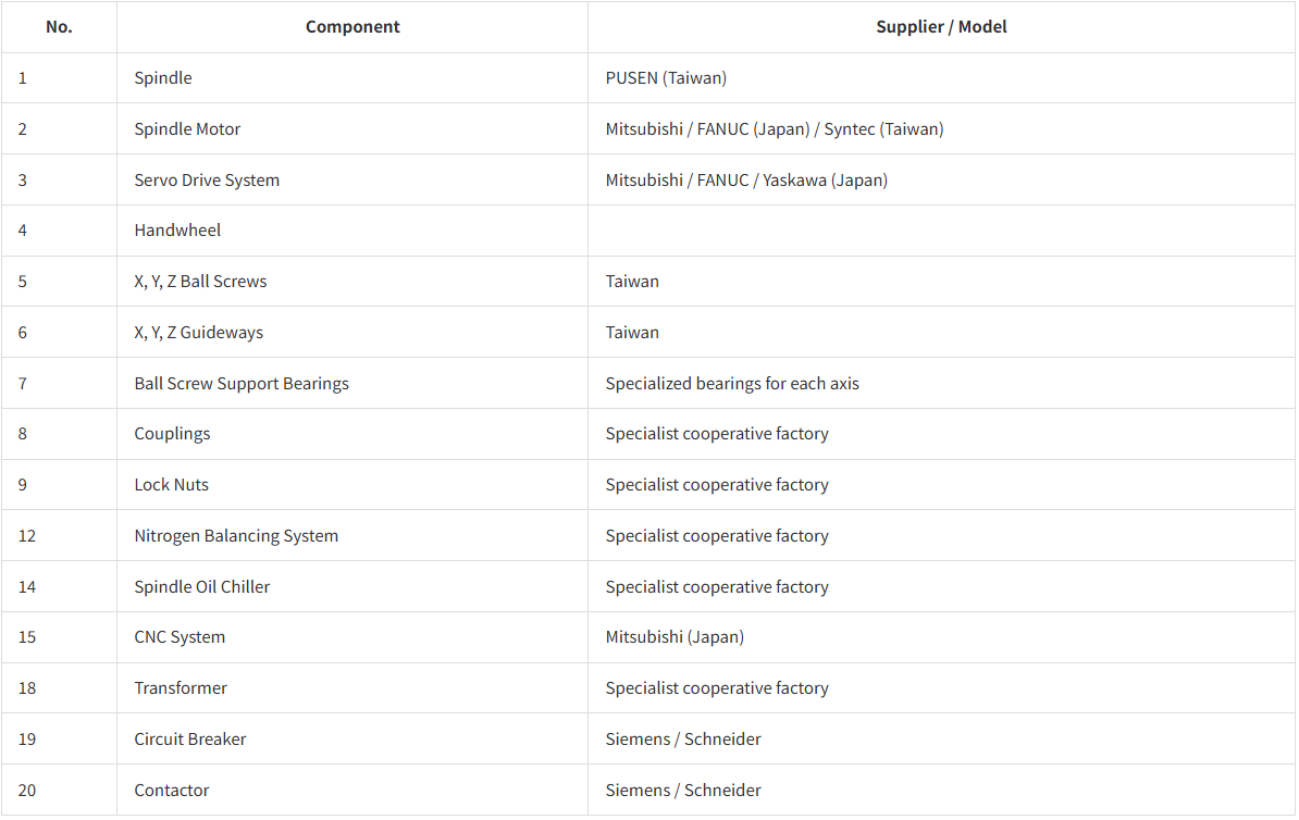
IV. Main Purchased Components
| No. | Component | Supplier / Model |
|---|---|---|
| 1 | Spindle | PUSEN (Taiwan) |
| 2 | Spindle Motor | Mitsubishi / FANUC (Japan) / Syntec (Taiwan) |
| 3 | Servo Drive System | Mitsubishi / FANUC / Yaskawa (Japan) |
| 4 | Handwheel | |
| 5 | X, Y, Z Ball Screws | Taiwan |
| 6 | X, Y, Z Guideways | Taiwan |
| 7 | Ball Screw Support Bearings | Specialized bearings for each axis |
| 8 | Couplings | Specialist cooperative factory |
| 9 | Lock Nuts | Specialist cooperative factory |
| 12 | Nitrogen Balancing System | Specialist cooperative factory |
| 14 | Spindle Oil Chiller | Specialist cooperative factory |
| 15 | CNC System | Mitsubishi (Japan) |
| 18 | Transformer | Specialist cooperative factory |
| 19 | Circuit Breaker | Siemens / Schneider |
| 20 | Contactor | Siemens / Schneider |
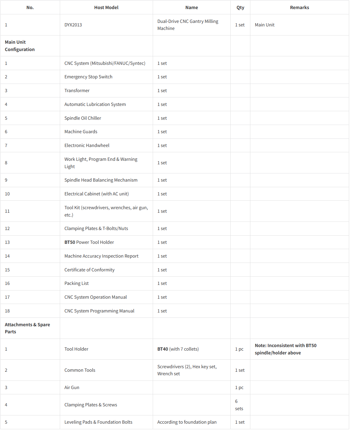
V. Packing List
| No. | Host Model | Name | Qty | Remarks |
|---|---|---|---|---|
| 1 | DYX2013 | Dual-Drive CNC Gantry Milling Machine | 1 set | Main Unit |
| Main Unit Configuration | ||||
| 1 | CNC System (Mitsubishi/FANUC/Syntec) | 1 set | ||
| 2 | Emergency Stop Switch | 1 set | ||
| 3 | Transformer | 1 set | ||
| 4 | Automatic Lubrication System | 1 set | ||
| 5 | Spindle Oil Chiller | 1 set | ||
| 6 | Machine Guards | 1 set | ||
| 7 | Electronic Handwheel | 1 set | ||
| 8 | Work Light, Program End & Warning Light | 1 set | ||
| 9 | Spindle Head Balancing Mechanism | 1 set | ||
| 10 | Electrical Cabinet (with AC unit) | 1 set | ||
| 11 | Tool Kit (screwdrivers, wrenches, air gun, etc.) | 1 set | ||
| 12 | Clamping Plates & T-Bolts/Nuts | 1 set | ||
| 13 | BT50 Power Tool Holder | 1 set | ||
| 14 | Machine Accuracy Inspection Report | 1 set | ||
| 15 | Certificate of Conformity | 1 set | ||
| 16 | Packing List | 1 set | ||
| 17 | CNC System Operation Manual | 1 set | ||
| 18 | CNC System Programming Manual | 1 set | ||
| Attachments & Spare Parts | ||||
| 1 | Tool Holder | BT40 (with 7 collets) | 1 pc | Note: Inconsistent with BT50 spindle/holder above |
| 2 | Common Tools | Screwdrivers (2), Hex key set, Wrench set | 1 set | |
| 3 | Air Gun | 1 pc | ||
| 4 | Clamping Plates & Screws | 6 sets | ||
| 5 | Leveling Pads & Foundation Bolts | According to foundation plan | 1 set |
VI. Training
The Supplier is responsible for providing technical training to the Buyer. The timing and personnel for training will be mutually agreed upon, with the training location at the Buyer’s site. The training content includes machine structure, performance and functions, CNC system, machine operation, and maintenance.
VII. After-Sales Service
-
The machine’s quality, specifications, and performance conform to the contract. Under conditions of correct installation, proper use, and maintenance, the warranty period begins from the date of acceptance. The Supplier will provide free warranty service promptly during the warranty period.
-
During the warranty period, damages caused by the user during loading/unloading/transportation, prolonged storage leading to external or internal mechanical damage, improper operation, or unauthorized disassembly/modification are not covered under the free warranty. The user must bear all repair costs.
-
After the warranty period expires, the Supplier will continue to provide maintenance services, charging standard rates for parts and labor.
-
If the Buyer fails to fulfill the payment obligations as per the contract after acceptance, the Supplier has the right to suspend after-sales services.
-
Before the full payment is settled by the Buyer, a password will be set in the system according to the agreed payment schedule, which will activate ten days after each payment due date. Once the payment is fully settled, the password restriction will be completely removed.
-
For faults caused by operational errors, the Buyer should notify the Supplier via phone or fax. The Supplier’s engineer will arrive at the Buyer’s site within 48 hours to resolve the issue. For major faults, the Supplier’s engineer must arrive on site for resolution.
VIII. Shipping Method: Truck transport. Freight costs are borne by the Supplier. Unloading upon arrival is the Buyer’s responsibility, with costs borne by the Buyer.
IX. Warranty Period: Free warranty for one year for manufacturing quality issues.